Bend Part feature does not include work features in Inventor
Inventor How To Bend A Part 60,352 views 220 Autodesk Inventor training and course tutorial how to bend a part for beginner at basic level with some easy command, check it out!!!Don't.

autodesk inventor bend part YouTube
A demonstration of the effects of moving the bend line reference plane when using "Bend Part" feature in Autodesk Inventor.This allows you to add a "fudge fa.

Bend Part Command Autodesk Inventor Part Tutorial Autodesk Inventor 2021 IN DEPTH YouTube
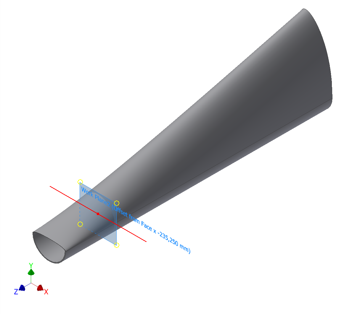
Create a bend in a part. Note: Bend Part is not intended for sheet metal applications. To begin, establish the bend plane. Either: Create a part, and position a work plane. or Sketch a parting line on a part face, or work plane. Bend Part requires both: a consumed sketch (such as an extruded face,) and a sketch that is visible, and unadaptive (such as line sketched across the extruded face.
Unexpected result using Bend Part feature in Inventor
To Create or Edit a Bend Note Annotate a bend centerline with fabrication data or instructions. Create a bend note On the ribbon, click Annotate tab Feature Notes panel Bend . In a flat pattern drawing view for a sheet metal part, select a bend centerline (or do a window selection for multiple bend centerlines).
Bend direction changes after "Rebuild All" of an Inventor sheet metal part
The bend feature places a new vertex in-between each selected vertex. The third vertex is automatically created and placed as the center of the bend. The Autodesk Inventor fold feature is another powerful tool that can help you design parts and assemblies in a more efficient way. It is designed to reduce the number of steps required to create.

Tutorial How to use "bend part" feature in Autodesk Inventor? GrabCAD Tutorials
Tutorial to use "bend part" feature in Autodesk Inventor. Step 1: Model a part and invoke a sketch on the surface about which you will bend it. Step 2: Create a line about which bending will initiate. Exit the sketch Step 3: Click on the arrow mark shown in the picture just below the "modify" tool bar. Step 4: Select bend part. Step 5:

Bend Part in Autodesk Inventor YouTube
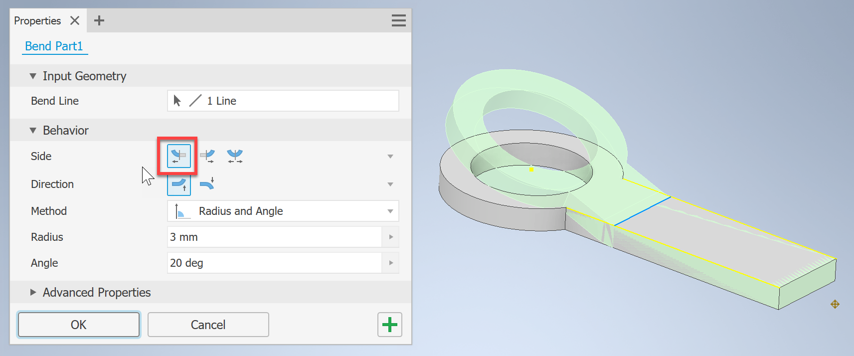
Use the Bend Part command to bend a portion of a part. What's New: 2021 First, you define the location of the bend, then you specify the side of the part to bend, the direction and other parameters of the bend. Note: Bend Part is not intended for sheet-metal applications.

Tutorial How to use "bend part" feature in Autodesk Inventor? GrabCAD Tutorials
To Bend Parts Use the Bend Part command to bend a portion of a part. What's New: First, you define the location of the bend, then you specify the side of the part to bend, the direction and other parameters of the bend. Bend Part is not intended for sheet-metal applications.

21 Bend Part trong inventor YouTube
A bend table for a particular part needs rows for only the angles used within the part. If a part uses only a single bend radius, a bend table requires only a single column. If a part has only 90 degree bends of a single bend radius, there is no benefit in using a bend table versus adjusting the KFactor value.

Inventor How To Bend A Part YouTube
Solution: On the ribbon, click Flat Pattern tab Manage panel Bend Order Annotation. The Bend Order glyphs appear. Right-click, and then click Sequential Reorder. Click the Bend Order glyph to number 1 in the sequence. Click the Bend Order glyph that you want to be next in the specified sequence. Repeat this step until you have defined the.

Tutorial How to use "bend part" feature in Autodesk Inventor? GrabCAD Tutorials
Use the Bend Part command to bend a portion of a part. First, you define the location of the bend, then you specify the side of the part to bend, the direction and other parameters of the bend. Note: Bend Part is not intended for sheet-metal applications.

Autodesk Inventor Bend Part Feature تعليم اوتوديسك انفنتور بالعربي YouTube
To Create or Edit a Bend Table Organize the properties of bends and their sequence. On the ribbon, click On the drawing sheet, select a flat pattern drawing view of a sheet metal part. In the Table dialog box: Click Column Chooser and add or remove columns from the bend table. Set format of the BEND ID string. Click OK to close the dialog box.

Autodesk Inventor Bend Part Feature YouTube
Tutorial to use "bend part" feature in Autodesk Inventor. The Computer-Aided Design ("CAD") files and all associated content posted to this website are created, uploaded, managed and owned by third-party users.
Unable to bend a sheet metal part in Inventor
How to Bend a Part | Autodesk Inventor Tech3D 82K subscribers Subscribe Share 63K views 8 years ago [Legacy, Unlisted] CAD Tutorials, Tips & Tricks Videos A tutorial-ish on how to use the.
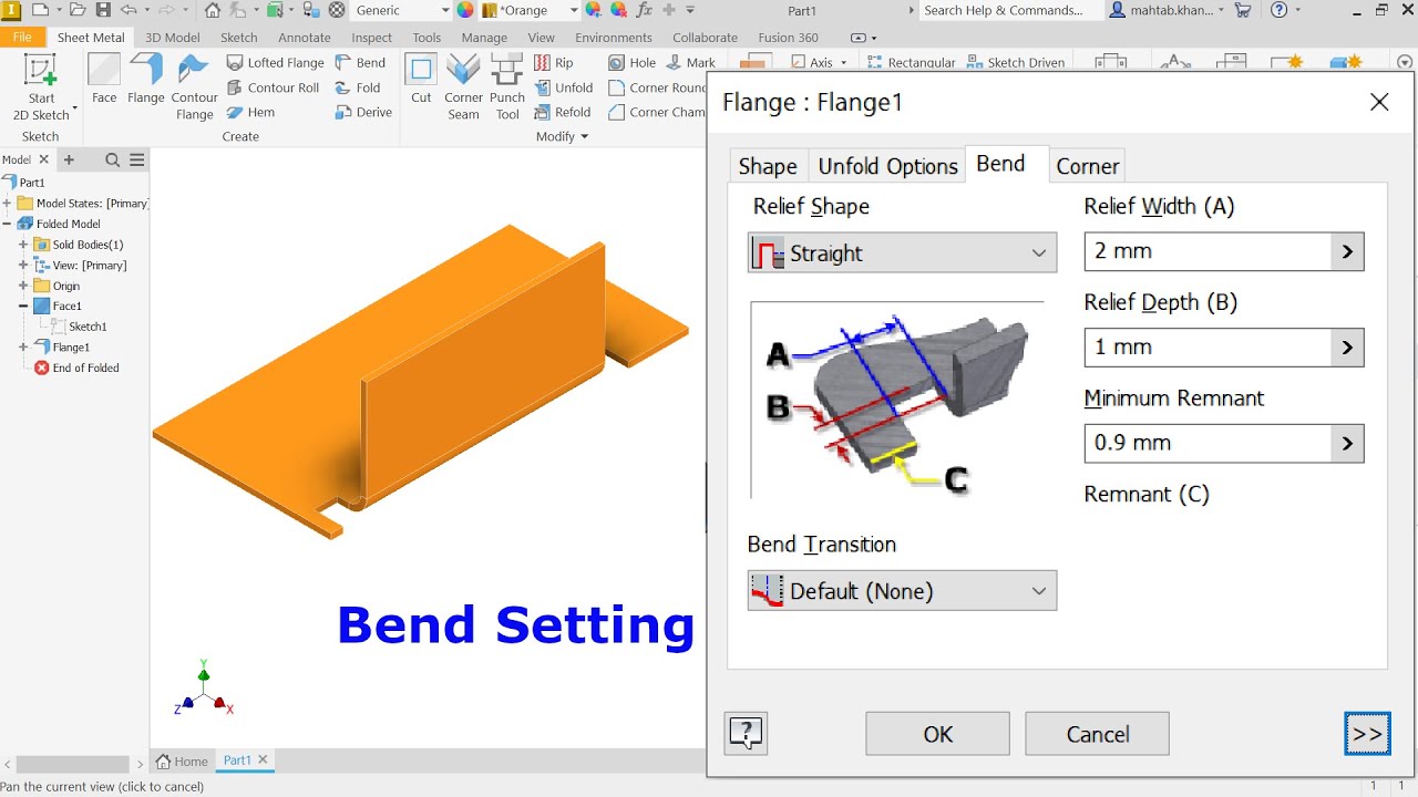
Autodesk Inventor 2023 Sheet metal Bend Setting YouTube
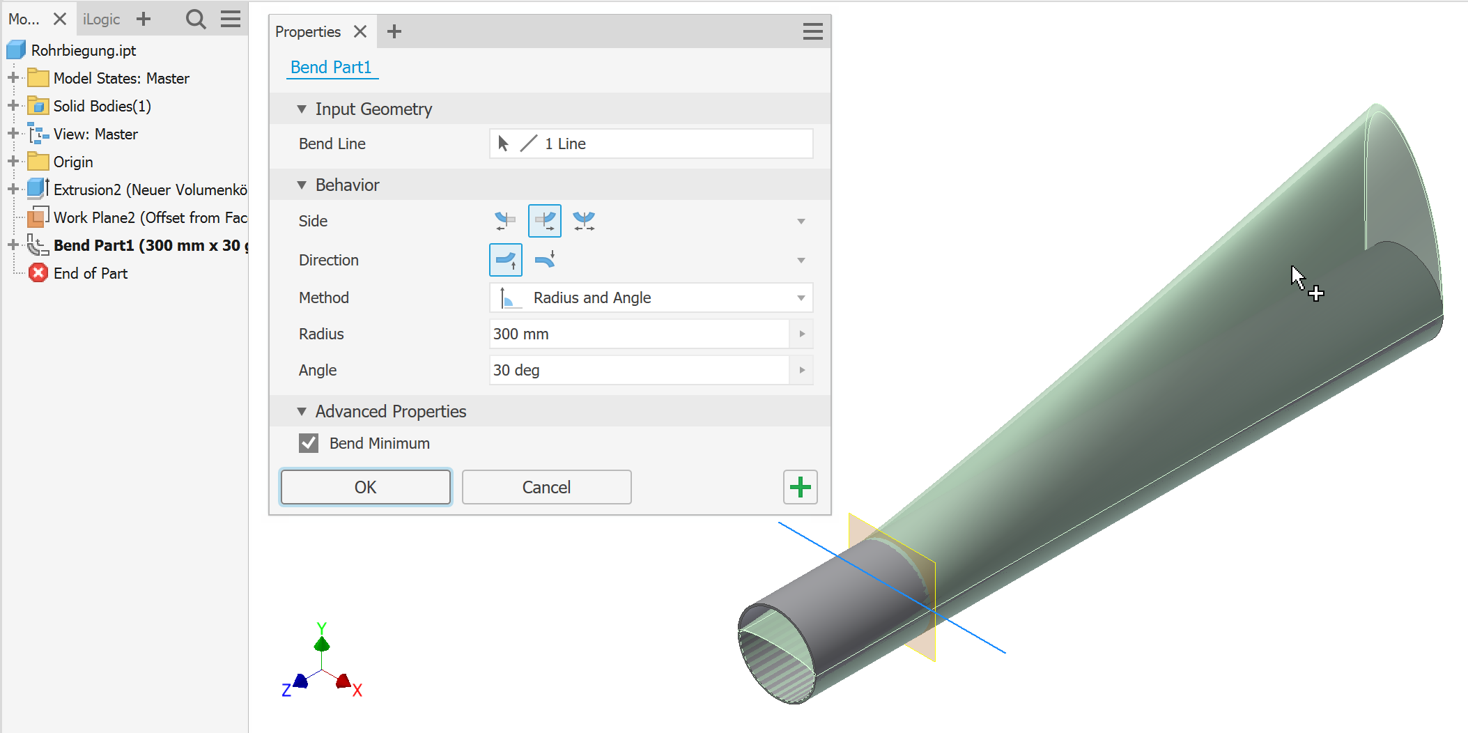
Autodesk Inventor > Parts > Part features > Create features > Bend features >. Bend Part Use Bend Part to bend a portion of a part. After you define the tangency location of the bend using a bend line, you can specify the side of the part to bend, the direction of the bend, and its angle, radius, or arc length. Access:.
Unexpected result using Bend Part feature in Inventor
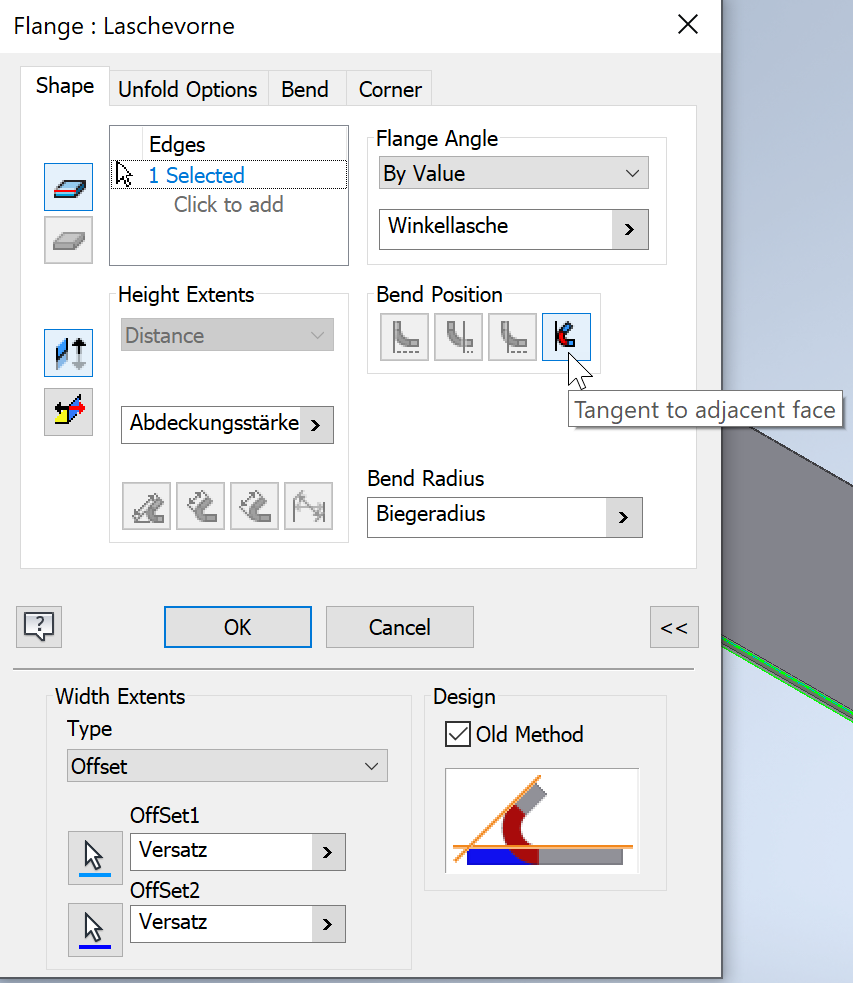
A single flange or contour flange feature in a sheet metal part can contain any number of bends. You can override default sheet metal styles from the Bend dialog box as you create your sheet metal bend. These settings include how the flat pattern unfolds, and the bend relief settings between faces.